
Ⅰ. Working Principle
Progressing Cavity Pumps (PCP) are high-quality, reliable and efficient pumping solutions designed for a wide range of applications. Known for their rugged construction and precise technology, these pumps are ideal for industries such as wastewater treatment, pulp and paper, chemical processing, food and beverage, and more.
With their unique design, these pumps provide continuous flow with low pulsation, unaffected by pressure and viscosity fluctuations. They are also self-priming and capable of handling high solids and abrasive materials. Easy to maintain and available in a variety of sizes and configurations, these pumps can be tailored to meet specific requirements.
Progressing cavity pumps are rotary positive displacement pumps used to transfer liquids. The technology behind these pumps lies in the unique design of the pump components, which essentially consist of an eccentrically rotating screw called a rotor and a stationary stator.
The ROTOR, made of steel or stainless steel, is often referred to a helical shaped screw with a defined pitch. The STATOR has a complementary helical geometry and has always one thread more than the rotor and is usually made of a flexible elastomer vulcanized into a metal tube. As the rotor rotates inside the stator, it creates sealed cavities that move from the suction to the discharge end of the pump, allowing the fluids to be pumped.
PCP technology provides a constant flow rate proportional to speed, regardless of the pumping pressure. This makes it an excellent product for applications involving high-viscosity, solid-laden or shear-sensitive fluids.
Another feature of progressive cavity pumps is their ability to handle fluids of varying viscosities, from aqueous to nearly solid. They can also handle aggressive, corrosive and abrasive fluids and overcome high system pressures, making them suitable for a wide range of industries, including oil and gas, mining, food processing and wastewater treatment.
Progressing Cavity pump technology offers energy efficiency advantages because the pumping process has minimal internal slippage and turbulence, reducing energy losses. The pumps can also operate at relatively low speeds, which reduces wear and extends pump life. Another advantage of the low speeds, combined with the resulting pumping chambers, is that the pumped media are conveyed extremely gently and without shear effects. The fluids remain homogeneous and there is no turbulence or swirling.
Ⅱ. Benefits and Features
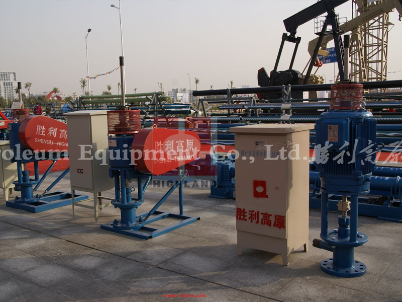
- Compared with electric submersible pumps, hydraulic plungerpumps and pumping units, Progressive Cavity Pumps have a simple structure and low one-time investment.
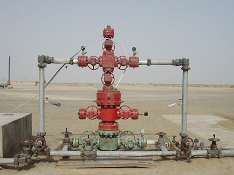
- The surface device has a simple structure and is easy to install, and can be directly connected with the wellhead casing four-way, and covers small area.
- High pump efficiency, low energy consumption and low management costs. Pump volumetric efficiency up to 90%, it is one of the lowest energy consumption and high efficiency of existing mechanical oil production equipment.
- Suitable for a wide range of viscosity oil and capable of lifting heavy oil.
- Adapt to high sand content wells and high gas content wells.
- Allowing a higher back pressure at the wellhead, and controlling the back pressure of the wellhead to be within 1.5 MPa or higher, which is beneficial to gathering and transporting in remote wells.
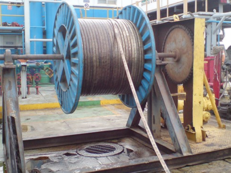
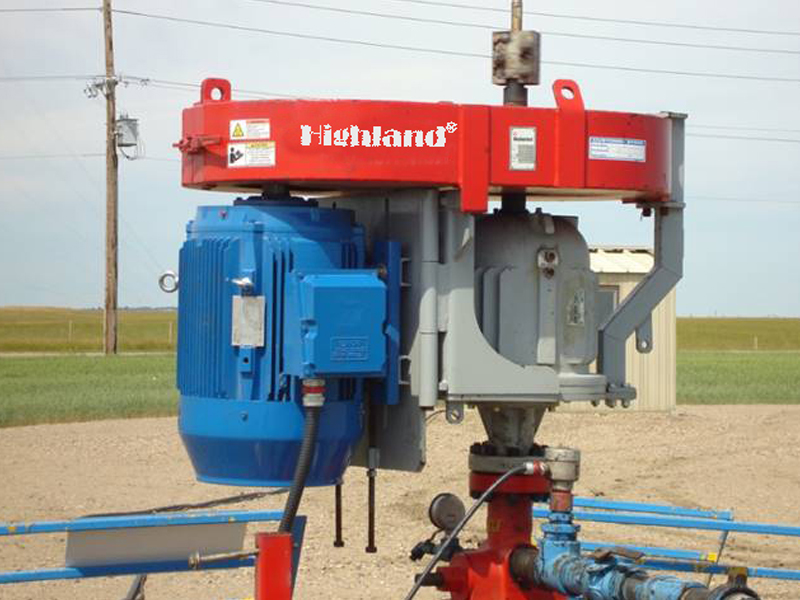
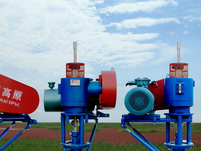
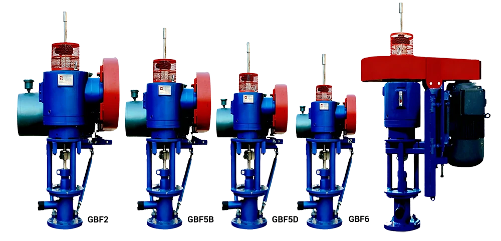
III. Surface Drive System
The surface drive is a specific facility to suspend and rotate the sucker rod, which in turn drives the downhole PC pump. Then fluid can be brought to the surface by the continuous movement of rotor within stator. When the unit is stop, the surface drive head absorbs reversion torque and prevents thread off. The mainly comprised parts are shown in fig 2.

IV. Motor
A Y series three-phase asynchronous motor is screwed tight on the motor skid and by changing the location of the motor, V-belt tightness can be adjusted effectively. Technical specifications are shown in table 1.
Table 1 Primary Specification
|
Model |
Rated Power(kW) |
Rated Voltage(V) |
Rated Current(A) |
Output Speed(RPM) |
Power Facto |
Efficiency(%) |
|
Y225M-4 |
45 |
380 |
84.7 |
1470 |
0.87 |
92.8 |
|
Y200L-4 |
30 |
380 |
56.8 |
1470 |
0.87 |
92.2 |
|
Y180L-4 |
22 |
380 |
42.5 |
1470 |
0.86 |
91.5 |
|
Y160L-4 |
15 |
380 |
30.3 |
1460 |
0.85 |
88.5 |
|
Y200L-6 |
22 |
380 |
44.6 |
970 |
0.83 |
90.2 |
|
Y180L-6 |
15 |
380 |
31.4 |
970 |
0.81 |
89.5 |
|
Y160L-6 |
11 |
380 |
24.6 |
970 |
0.78 |
87.0 |
|
Y132M-4 |
7.5 |
380 |
15.4 |
1440 |
0.85 |
87.0 |
|
Y160M-6 |
7.5 |
380 |
17.0 |
970 |
0.78 |
86.0 |
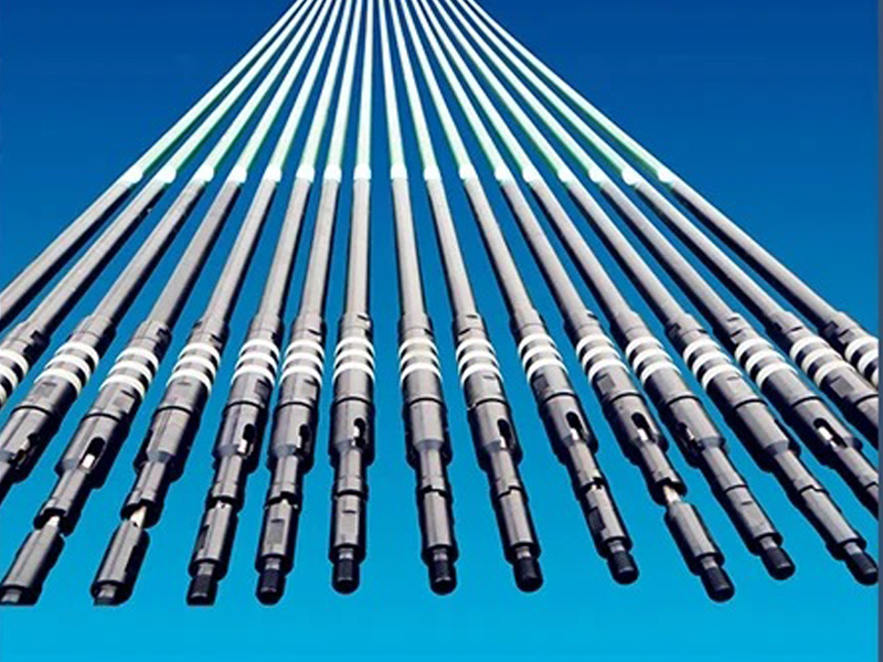
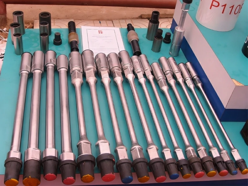
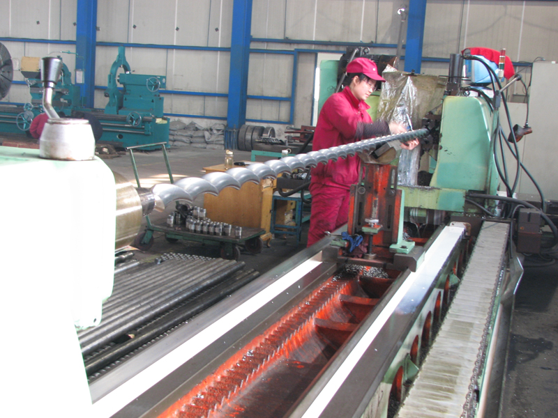
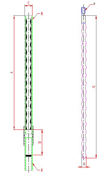
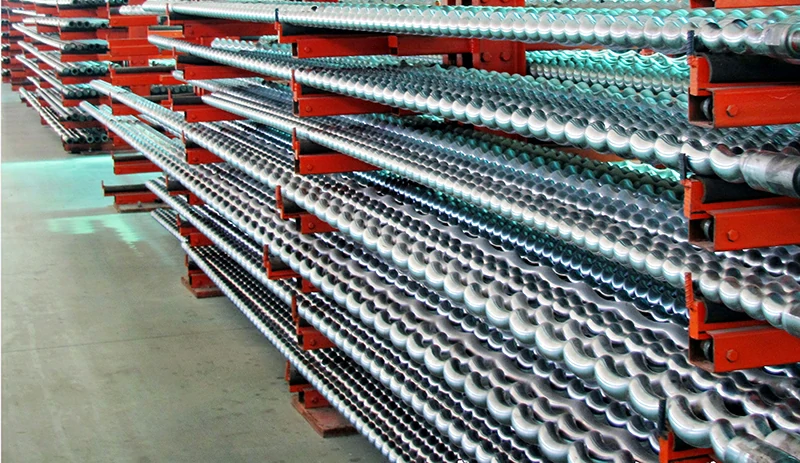
V. Downhole PC Pump
The PC pump brings the fluid from downhole to the surface and discharges it under a certain pressure. It consists of a rotor and a stator.(see fig14) The dimensions of rotor and stator are shown in table 13.
VI. Downhole PC Pump Specifications
|
Model |
Capacity ml/r |
Capacity m3/d@100r |
Capacity bbl/d@100r |
Grade |
Lift(m) |
Lift(Ft) |
|
LB40-21 LB40-27 LB40-42 |
40 |
5.8 |
36 |
21 27 42 |
960 1200 1900 |
3100 3900 6200 |
|
LB50-12 LB50-27 LB50-40 |
50 |
7.0 |
44 |
12 27 40 |
600 1200 1800 |
1900 3900 5900 |
|
LB75-12 LB75-21 LB75-27 LB75-40 |
75 |
10.8 |
68 |
12 21 27 40 |
600 960 1200 1800 |
1900 3100 3900 5900 |
|
LB120-12 LB120-27 LB120-36 LB120-40 |
120 |
17.3 |
109 |
12 27 36 40 |
600 1200 1600 1800 |
1900 3900 5200 5900 |
|
LB190-27 LB190-33 LB190-40 |
190 |
27.4 |
172 |
27 33 40 |
1200 1500 1800 |
3900 4900 5900 |
|
LB200-25 LB200-33 LB200-40 |
200 |
28.4 |
181 |
25 33 40 |
1150 1500 1800 |
3800 4900 5900 |
|
LB300-21 LB300-27 |
300 |
43.2 |
272 |
21 27 |
960 1200 |
3100 3900 |
|
LB400-20 LB400-30 |
400 |
57.6 |
362 |
20 30 |
910 1300 |
2900 4200 |
|
LB500-14 LB500-21 |
500 |
72.0 |
453 |
14 21 |
640 960 |
2100 3100 |
|
LB600-12 LB600-14 LB600-21 |
600 |
86.4 |
543 |
12 14 21 |
600 640 960 |
1900 2100 3100 |
|
LB800-16 |
800 |
115.2 |
725 |
16 |
730 |
2400 |
|
LB1100-10 LB1100-12 LB1100-14 LB1100-16 |
1100 |
158.4 |
996 |
10 12 14 16 |
460 550 640 730 |
1500 1800 2100 2400 |
|
LB1400-14 |
1400 |
210.6 |
1325 |
14 |
640 |
2100 |
|
LB1600-12 |
1600 |
230.4 |
1450 |
12 |
550 |
1800 |
|
LB230DT27 LB230DT40 LB230DT50 |
230 |
33.1 |
208 |
27 40 50 |
1200 1800 2300 |
3900 5900 7500 |
|
LB375DT27 LB375DT33 LB375DT40 |
375 |
54.0 |
340 |
27 33 40 |
1200 1500 1800 |
3900 4900 5900 |
|
LB460DT27 LB460DT33 |
460 |
66.0 |
417 |
27 33 |
1200 1500 |
3900 4900 |
|
LB580DT18 LB580DT21 LB580DT27 LB580DT33 |
580 |
83.5 |
525 |
18 21 27 33 |
820 960 1200 1500 |
2700 3100 3900 4900 |
|
LB800DT20 |
800 |
115.2 |
725 |
20 |
910 |
2900 |
|
LB990DT14 |
990 |
142.6 |
897 |
14 |
640 |
2100 |
|
LB1200DT16 LB1200DT21 |
1200 |
172.8 |
1090 |
16 21 |
730 960 |
2400 3100 |
|
LB2000DT16 |
2000 |
288.0 |
1810 |
16 |
730 |
2400 |
|
LB1100TT14 LB1100TT18 LB1100TT21 LB1100TT27 |
1100 |
158.4 |
9960 |
14 18 21 27 |
640 820 960 1200 |
2100 2700 3100 3900 |
VII. Rubber
After years study and development, stator rubber of our PC Pump has achieved a wonderful facility of production. International advanced rubber laboratory has been built. Advanced stator rubber formula can be developed all by ourselves. Rubber performance test and rubber impregnation technology have gained great success.
Table 15 Main Rubber Formulas for Stator
|
Code |
Rubber Type |
Application |
|
GY-1 |
Simple oil |
Used in the petroleum containing water and CO2. Below 80℃. |
|
GY-2 |
Clean oil |
Used in the fluid containing aromatics and CO2. Below 90℃. |
|
GY-3 |
Viscous and sandy oil |
Moderate acrylonitrile cut. Used in fluid with high sand cut and water. Below 120℃. |
|
GY-4 |
Hightemperature 130℃ |
Used in fluid containing CO2 and H2S with good mechanical property. Below 130℃ |
|
GY-5 |
Hightemperature 150℃ |
Used in fluid containing H2S. Working temperature reaches up to 150℃.Perfect mechanical property. |